home |  electronics |  toolbox |  science club |  tuxtalk |  photos |  e-cards |  online-shop

http://tuxgraphics.org/electronics


Content:
By Guido Socher


A hobby power over ethernet solution (homebrew PoE)

[Illustration]

Abstract:

Every once in a while we get suggestions to build a PoE (Power over Ethernet) version of the tuxgraphics ethernet board. This is certainly a nice idea but it seems that most people who want PoE want actually not IEEE 802.3af .

_________________ _________________ _________________


What is PoE?

Ethernet has 4 wire pairs (8 wires) and for 10/100 Mbit only two of them are used. PoE is being standardized in IEEE 802.3at. PoE implements two ways of supplying DC power over the Ethernet cable. In mode-A the wire pairs which are also used for data transmission are used to supply the power. This would be pairs 2 and 3 (pins 1,2 and 3,6). Mode-A is also known as "Phantom Power". In mode-B the power is supplied via the wire pairs which are unused. PoE requires special switches to supply the power over the ethernet lines or one can use a powering device which is inserted into the line. This switch/powering device is called Power Sourcing Equipment (PSE). It is the PSE that decides which of the two modes to use. The equipment that is supplied with power (Powered Device , PD) should be capable of handling both mode-A and mode-B.

To hopefully not destroy existing equipment those powering devices (PSE) and switches test the line with a probe voltage and conclude form there if the end device is capable of PoE.

Once started up the PSE supplies 48V and 100mA to 400mA. The high voltages are needed because ethernet cables can be very long (e.g 100m). A high voltage minimizes the loss over long lines.

Most ethernet chips use either 5V or 3.3V. A switched voltage regulator is needed to convert the 48V on from the ethernet wire into something usable.

PoE is fairly expensive. A simple home and office switch might cost 10 to 20 dollar. PoE switches cost about ten times more.  

Homebrew PoE

PoE is a nice idea but to me it seems that many people want actually more a USB-like solution where a low voltage is supplied via a short cable (few meters). The ethernet equipment can then directly be powered from the ethernet cable without complicated electronics and logic.

How to power the tuxgraphics ethernet board with a "Homebrew PoE" solution?

We will use the spare wires in the ethernet cable to supply the power. That is: pair 1 (pins 4,5) will be the positive wires and pair 4 (pins 7,8) will be the negative wires. The data wires (pairs 2 and 3) are not touched.

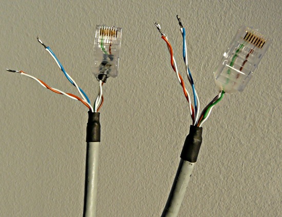
Using an RJ45 crimp-tool we will make a special break-out cable as shown below. We take the "power wires off" before connecting the cable to the RJ45:
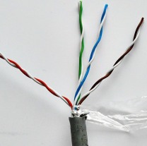
I recommend to use white-green/green as data wire pair 2 (wires 1,2) and white-brown/brown as data wire pair 3 (wires 3,6). This leaves you then with white-orange/orange and white-blue/blue for the power wires and it is a common convention that blue is minus while red or orange is plus.

RJ45 Pin#Color code nameColorUse
1white-greenData transmit+
2greenData transmit-
3white-brownData receive+
NC (4)orange+ DC power
NC (5)white-orange+ DC power
6brownData receive-
NC (7)white-blue- DC power
NC (8)blue- DC power


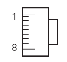
The wire numbers marked with NC are not connected on the RJ45 plugs. The picture on the right shows how the pin numbers are to be counted on the RJ45 plug. The plug is shown from the front. The cable would be behind.

For a cable length of up to 20 meters (66ft) I recommend 6.5 volts DC as supply voltage. You loose less than 0.02V per meter (3ft) of cable with the ethernet board consuming about 140mA of current. A 0.14mm2 (AWG26) wire has about 0.1 Ohm per meter (3ft). You should have 5V or more before the voltage regulator of the board. Note that you should try to keep the voltage at the regulator on the board below 10V otherwise it becomes very hot and requires good cooling. The voltage regulator on the tuxgraphics ethernet board can then be directly connected to the breakout wires (white-blue/blue and white-orange/orange).


How to use an ethernet crimp-tool

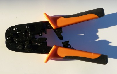
To make your own ethernet cable as described above you will need a special RJ45 crimp-tool. The contacts of the RJ45 are pressed directly into the wire. The insulation of the wire is not taken off before you crimp. You cut the wire at the right length and then you insert it into the the plastic rj45. The contacts, when pressed-on with the crimp-tool, cut through the insulation into the wire.

The crimp-tool will also squeeze the plastic of the rj45 at the end to form some pull-relief. In our case not all wires are used. The pull relief will therefore not function as the cable is too thin. You can either slide some tubes over the wires before you crimp to make them fatter or you can use some hot-melt glue to fix the wires mechanically after the crimping.  

References/Download


© Guido Socher, tuxgraphics.org

2009-11-03, generated by tuxgrparser version 2.57